1-Wire Surge Protection
Background
A number of people running weather stations have had problems with nearby
lightning strikes -- myself included. Typically the failure is of the DS9097U.
In some cases, temperature sensors are also lost. I beleive that it also
can cause problems with the raingauge. There is more information on the
sensors
that I have.
What happens during a lightning event?
The lightning strike causes a large magnetic field to be created -- this
induces significant voltages in long pieces of wire. These voltages can
exceed 1kv per meter of wire (if the strike is within 100 meters). In a
real network, some of these voltages cancel out, but there are still large
voltages and energies to be handled. The big voltages will be 'common mode'
-- i.e. the same voltage will be induced on each conductor. However, depending
on the twisting in the cable that you use, you can also get a much smaller
differential voltage induced.
The differential voltages are enough to kill sensors that are attached
to the ends of long runs of cable. The common mode voltage doesn't impact
them at all.
The common mode voltage plays havoc with the DS9097U and the computer's
serial port. Typically what appears to happen is that the ESD protection
diode (DS9503) sacrifices itself to prevent the energy from frying the
computer completely.
What doesn't work
I had my 1-wire network plugged into a standard telephone surge protector.
It didn't protect the DS9097U. However, a telephone circuit can have up
to 200V on it in normal use, and this is more than enough to fry the ESD
diode.
What I'm doing now
I have two circuits -- one for protecting sensors, and one for protecting
the DS9097U. The inline circuit looks like this.
The idea is that one of the diodes (both 1N4004) prevents GND from
going above DATA. The 12V Zener protects the DATA from going more than
12V above GND. The other diode is reduce the capacitance of the circuit
to an acceptable level. The 47Ohm resistor acts as a current limiter during
events -- it limits the current to about 300mA.
I chose a 12V zener as that is the lowest voltage which has a small
leakage current (5uA). All the parts are supposed to be able to handle
in excess of 30A, and so they are unlikely to die in service.
Happily this circuit can be layed out in a straight line.
I just put a bit of heatshrink tubing around the components and shrunk
it. It made a nice package.
Suppressor for DS9097U
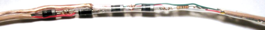
This is a picture of the main surge suppressor that I built. I should
have taken the picture before I encased it in heatshrink tubing. Also,
the ground wire really should come out of the other end of the tubing,
but I was following my diagram! Note that in order for this circuit to
be effective, you must attach the ground wire to the chassis of the computer
-- or something with a very good ground.
The parts are:
-
Diodes: 1N5404GICT -- 3Amp 400PIV diode
-
Zener (TVS): 1.5KE10ACCCT -- 10 Volt 1500 Watt Unidirectional TVS. I got mine from Digikey.
The datasheet for the part indicates that it has a response time of 1 picosecond -- i.e. effectively instantaneous!
-
Resistors: 22 Ohm 1/2 Watt.
The actual circuit looks like:
The physical layout is:
Yes -- I know that I haven't been consistent with using a dot to indicate
wire joins. If two wires are crossing, and there is no dot, then the wires
do not touch. I'm too tired (as I write this) to fire up my circuit design
package to draw pretty diagrams.
The diodes and TVS part are large and I had to turn the temperature
up on my soldering iron to get the solder to flow properly.
You might ask, why choose devices that can handle 60 Amps -- you can't
possible get that much down the cable from the outside? The answer is that
I bet you can (for a short enough time). The lightning pulse induces current
for less than a millisecond. The cable has a resistance of under 0.1 ohm/meter.
Thus 60 amps translates into 360 Watts/meter, or 0.36 Joules/meter/millisecond.
This is not going to heat the cable up noticeably, and so I guess that
it will survive! We just need to make sure that the surge suppressor survives
-- hence the apparent overkill.
Principle of Operation
It works in very much the same way as the first suppression device. The
difference is that the chassis ground wire must be no higher than the network
ground wire, and the network data wire is no more than 10 volts or so above
the chassis ground. The reason for having two resistors is to protect the
DS9097 against a large common mode positive surge -- both network ground
and network data will go up to about 14 volts or so, and the 22 ohm resistor
will limit the current into the DS9097 to under 1 Amp. This can be handled
by the ESD protection diode.
Does it work?
Yes! No lightning has come anywhere near since I added this circuit! Seriously,
I don't have any way of testing this stuff apart from with a multi-meter.
I know that what I have built corresponds with what I have drawn. I got
the circuits from a booklet put out by one of the TVS companies, and the
circuits look right.
What are other people doing?
You can check the mailing list. If anybody wants to give me a link to what
they are doing, I'll add it to this page.
Comments: Philip
Gladstone
Last Updated: October 8, 2001